
The fall quarter consisted mostly of researching and design work, where we worked to complete the design for prototyping the preliminary design report which is additional documentation that the team needs to complete for the competition. Software development focused on creating a ground station capable of receiving and displaying telemetry data from the CanSat’s sensors, while hardware focused on having electrical and mechanical prototype designs for the following quarter to test.
Winter quarter was dedicated to practicing our presentation for the Competitions Preliminary Design Review (PDR). All subteams worked focused on their forces to complete the presentation and practice presentation times.
This Spring quarter involved us finally taking all our research and designing over the past year and implementing them into a physical solution. Electrical components were ordered, container segments were printed and assembled, and the various performances of our design were tested to verify requirements compliance.
Telemetry is an automated communication process in which measurements of data are taken remotely for monitoring and recording. History of telemetry in aerospace can be traced back to the 1930s with the invention of balloon-borne radiosonde. Since then, size and complexity of aerospace telemetry systems have grown significantly, and such systems are commonly used in rapidly moving vehicles.
The CanSat competition, sponsored by the American Astronautical Society (AAS), offers student competitors to be involved in the complete life cycle for the development of a telemetry reporting payload system. University students are to design and build a system, complying with a set of competition guidelines, and compete at the end Spring quarter.

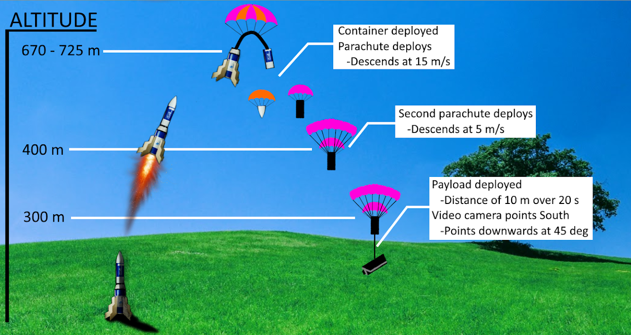
Design a container that will be stored in and deployed from a rocket. The container should have predetermined descent rates based on altitude, controlled by a total of 2 parachutes: at above 400m, the container should descend at 15m/s, at below 400m, the container should descend at 5m/s. At 300m, the container should deploy a payload, attached to the container by a tether and consisting of a camera, at a decent rate of 0.5m/s, until the payload is 10m away from the container. The camera from the payload should face South and 45 degrees below the horizon at all times. The container should report telemetry while descending.
The overall design consists of three key components in order for the CanSat to function effectively. They are separated into the three parts that make up the CanSat.
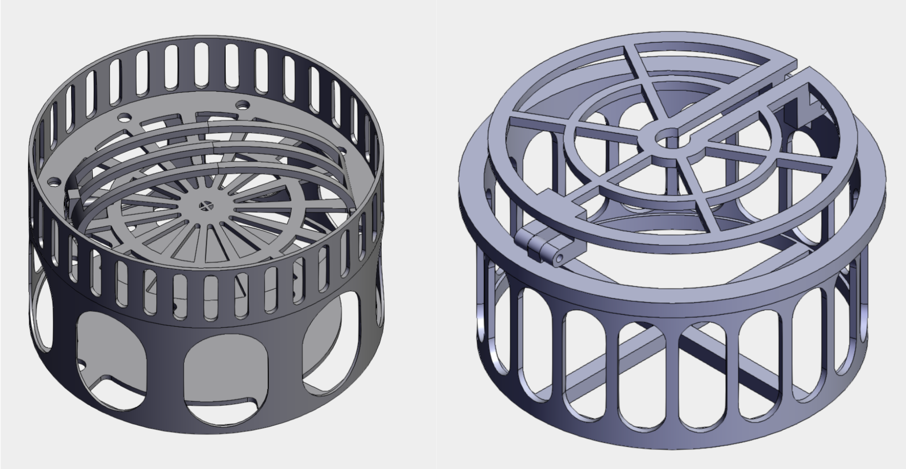
The first part of the CanSat is the top cap. The purpose of the top cap is to stow both the first and second parachutes for deployment at their specific altitudes in order to slow down the descent rate of the CanSat. The key component in the top cap is the secondary parachute deployment mechanism.
The second part is the body. Is it the middle cylinder that connects both the top cap and the payload (third component). It is the largest part which is used to house the pulley system, the key component of the body, which is used to deploy the payload via 10 meter long tether(s).
The third part is its own key component: the payload. The payload is the “cargo” of the CanSat which sits at the bottom of the CanSat. It houses a camera that requires a very specific orientation (cardinal direction and angle) along with its necessary electronics.

The first parachute sits atop of Top Cap while tied to it. The first parachute deploys naturally as it falls out of the rocket when it separates via ejection charges. The top cap must be able to house the second parachute until its specified deployment time, along with the electronics needed to power the mechanism.
While the first parachute sits above, the second chute is held down by a lid with a spring hinge mechanism. In order to hold down the lid, either nichrome wire or a solenoid were debated being used. Given that the solenoid and nichrome wire had similar traits, but the solenoid offered better strength and reusability, the solenoid was chosen for our second parachute deployment mechanism.
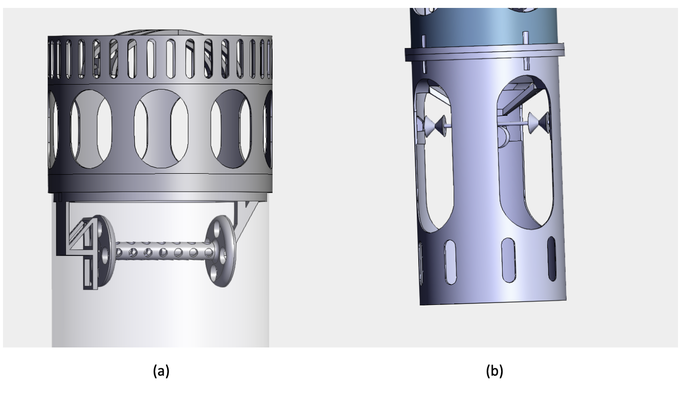
The body is the largest part of the CanSat. The pulley system is housed here along with its electronics i.e. servos, circuits, battery. The pulley system is an important component for CanSat as its job is to lower the payload 10 meters down with tethers. When the pulley system is active, the CanSat will be descending at a rate of 5 m/s (+/- 2 m/s) and wind will be the main factor contributing to instability of the CanSat. Due to this, stability is a high priority factor for the payload. This can be accomplished with a four tether system.
Figure: Front views of two different pulley systems in the container body. Both incorporate four tether designs in order to maximize stability when the payload descends.

A significant concern with the pulley system is the possibility of the tethers tangling while they descend. In order to prevent this, the four tethers need to be independent from each other to minimize interaction. Both designs With four tethers, the possibility of each individual tether spinning is reduced.
The design on the left utilizes one “spool” to wrap all four tethers which is powered by a servo motor. The benefit with this is that there is less weight required for the pulley system meaning less torque required for the servo motor.
The right design utilizes four spools where each tether runs through. The benefit with this is that each tether is isolated and spread apart across four points, improving stability for the payload descent.
Modifications and improvements are continuing to be made for the pulley system. As the project is still in the preliminary stages, different concepts are being experimented with. For example, the use of four smaller servos powering four spools is an idea that is being considered.

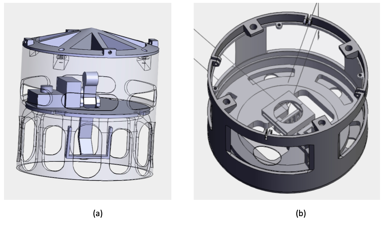
The payload is another important component for the CanSat. Our goal is to ensure that the camera installed must face 45° downwards, due South. Evidently, the payload must have a wide space for the electronics to be mounted. Preferably, the payload should be light in order to reduce the load on the pulley system. The camera's view should be obstructed as little as possible to ensure a wide viewing angle. Additionally, the camera and its electronics must be able to survive the impact during landing completely intact. Due to these reasons, special attention was placed on the payload’s design.
Figure: Two payload designs. Both utilize two servos that control pitch and yaw of the camera with a rotating plate for the cardinal direction and a lever for the angle control.