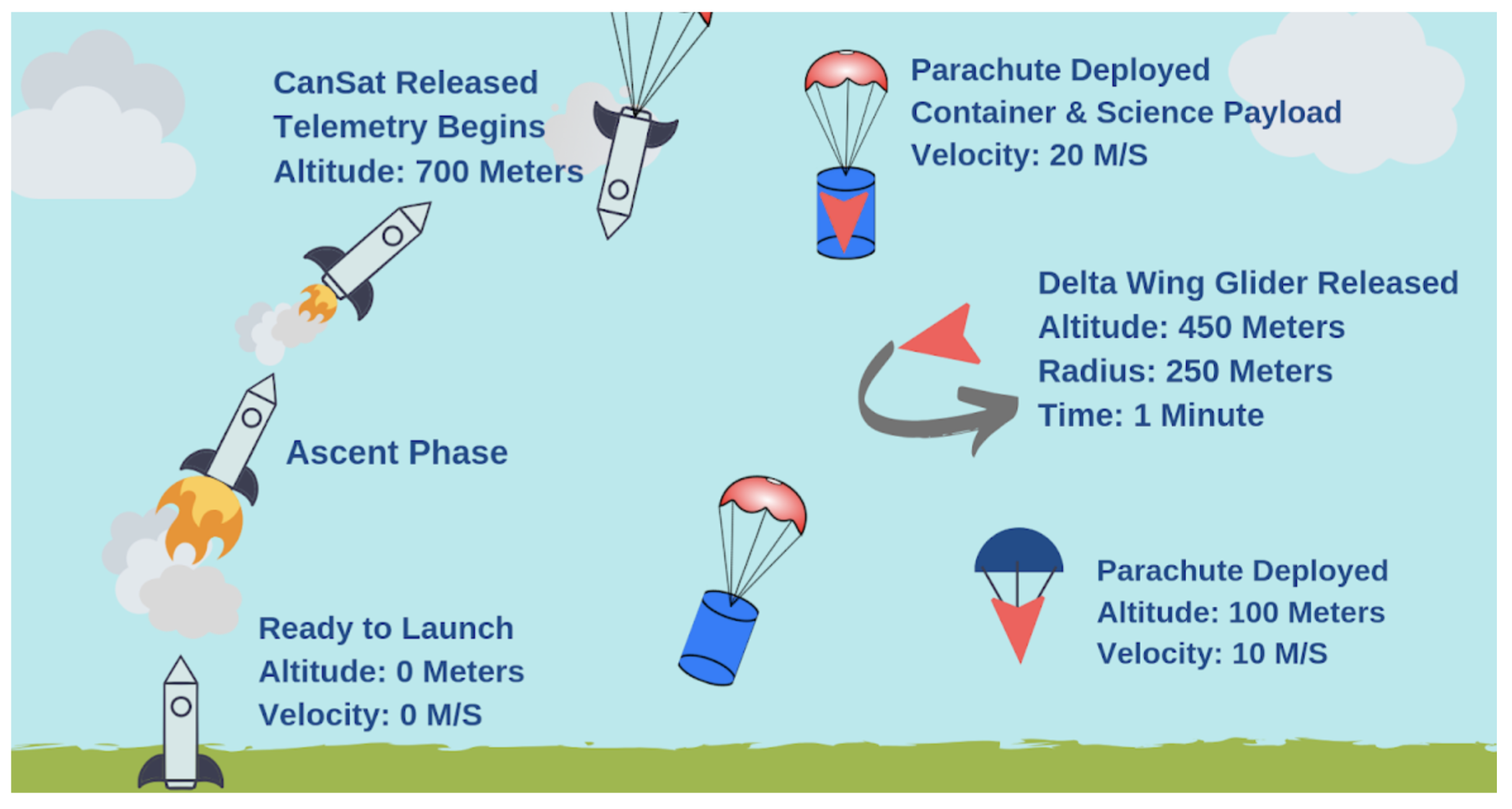
The CanSat Competition is an international design/build/fly engineering competition taking place at Virginia Tech University. In this year’s mission, the CanSat will be launched to 700m using a high-powered model rocket and then perform a controlled descent while transmitting data from its onboard sensors to a ground station computer. The CanSat consists of a container and science payload. Initially, both descend under a parachute. At 450m, the payload is released and continues its descent as a delta wing glider. The glider then descends in a circular pattern of radius 250m for one minute while staying above the altitude of 100m. Finally, the delta wing glider releases its own parachute and descends at 10 m/s back to the ground.
Our team represents UCI in this international competition. We have three deliverables throughout the year: the Preliminary Design Review, Critical Design Review, and CanSat hardware to launch at the competition. We follow a yearly design cycle, adhering to deadlines and requirements imposed by the competition. This ensures all teammates gain experience with the full engineering design process.
Figure: Diagram of 2019 - 2020 CanSat Mission
As a competition project, our problem statement has two parts. Our technical goal is to design and build a CanSat, which consists of a container and science payloads. The CanSat descends from an altitude of 670 to 725 m; first the container and payload descend together under a parachute at a velocity of 15 m/s. The first payload is then released at 500 m from the container and begins rotating rapidly to descend at a rate less than 20 m/s. At 400 m, the second maple seed will be released.
The Payload must be equipped with sensors for air temperature, air pressure, and rotation rate. It must be capable of transmitting this data in real-time to the container. The container must relay all data as well as have a GPS sensor, pressure sensor, battery voltage measurement, and audio beacon. The scope of our project is designing and building the CanSat and ground station. The launch system (a high-power model rocket) is provided by the competition organizers to standardize launches. The CanSat container must protect the science payload from damage during the launch and deployment.
Our overarching goal is to perform well in the CanSat Competition. Additionally, we need to ensure all CanSat teammates gain practical experience in the engineering design process. Finally, we must ensure our project satisfies the MAE Department’s requirements for senior design and represents UCI well at design reviews and the CanSat Competition.
In addition to the container and payload structure, the CanSat must be equipped with sensors for environmental conditions (temperature, pressure, GPS position, altitude, particulates) and system performance (orientation and battery voltage). These sensors must adhere to specification requirements set by competition. Please refer to the Requirements section for specifics.
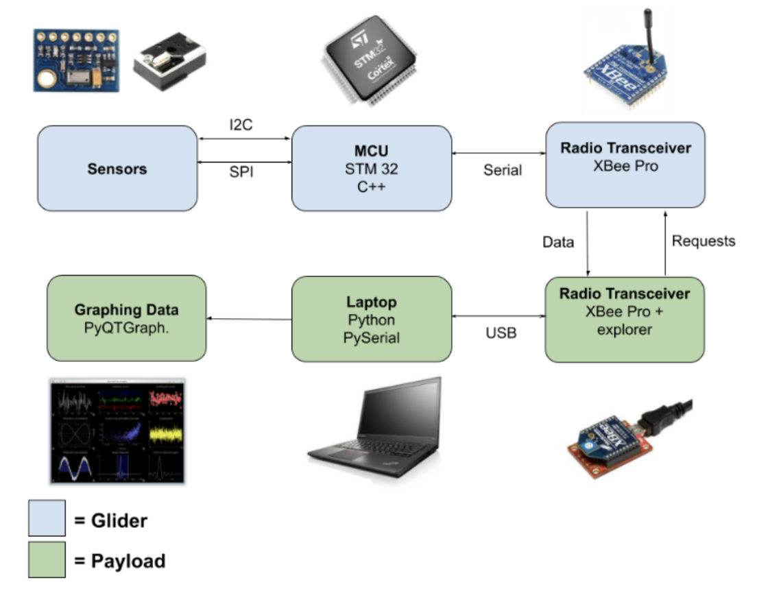
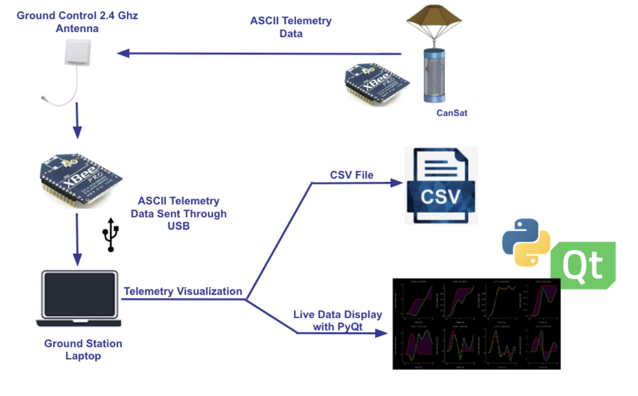
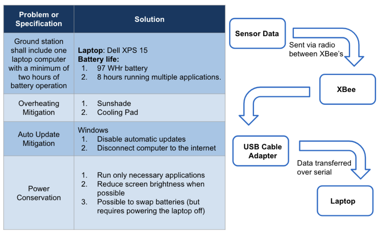
The CanSat must also be capable of transmitting this data in real-time to a ground station computer. The ground station will consist of primary (and backup) laptop, handheld receiver, and an XBEE radio. Packets of data will be sent wirelessly to the ground station and will be plotted in real time on a graphical user interface. These packets will also be saved in a comma separated value file (.CSV) for further analysis and plotting in the Post Flight Review after the competition.
The scope of our project is only designing and building the CanSat and ground station. The launch system (a high-power model rocket) is provided by the competition organizers to standardize launches. The CanSat container must protect the science payload from damage during the launch and deployment.
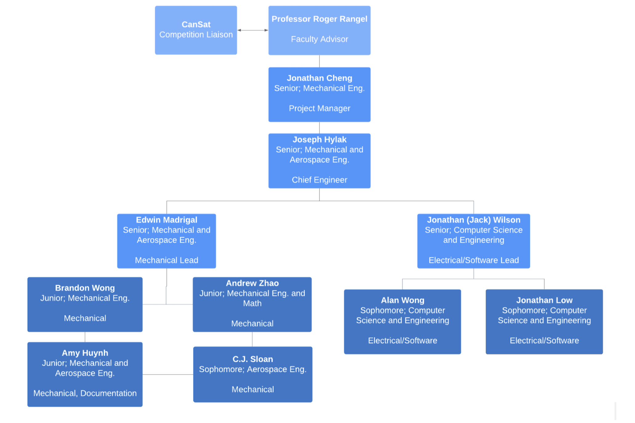
The CanSat team leads include Jonathan Cheng, Joseph Hylak, Jonathan Wilson and Edwin Madrigal, as shown in the organizational chart above. Jonathan Cheng overlooks and contributes to both the hardware and software sub-teams and works on administrative tasks for the team. Joseph Hylak is in charge of finalizing designs and ideas developed by the mechanical team as well as integration of electrical and software components. Jonathan Wilson manages the software and electrical team, consisting of Alan Wong, and Jonathan Low. Edwin Madrigal manages the hardware team consisting of Brandon Wong, Andrew Zhou and C.J Sloan.
Team Leads ensure that all team members are making progress with the design, manufacturing, and testing of the CanSat probe. They also provide guidance and advice for team members by creating and delegating tasks for each team member. Every student is involved with researching mechanical components of the CanSat. Hardware members focus on the mechanical structure while software members focus on the probe controls and telemetry, as well as developing the data plotting and logging features of the ground station.
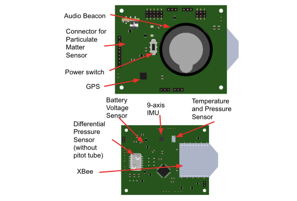
Most of the CanSat sensors are soldered directly onto the custom printed circuit board (PCB). The battery voltage measurement is integrated onto the PCB.
The MS5611 provides altitude, temperature, and pressure readings. The XA1110 provides GPS latitude, longitude, altitude, and time. It can report the number of GPS satellites tracked. The 5525DSO provides readings of airspeed, which works in conjunction with a pitot tube. The GP2Y1010AU0F provides particulate concentration readings.
Figure: CanSat Sensors placed on the PCB
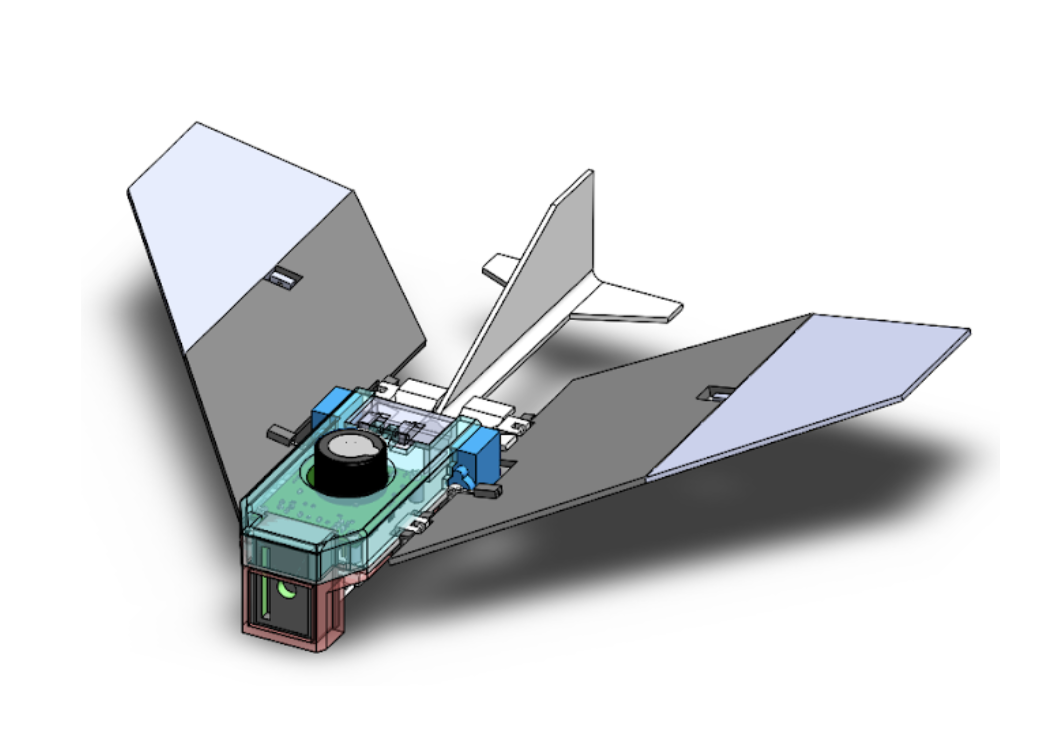
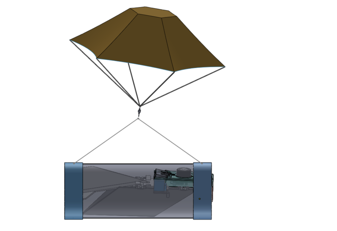
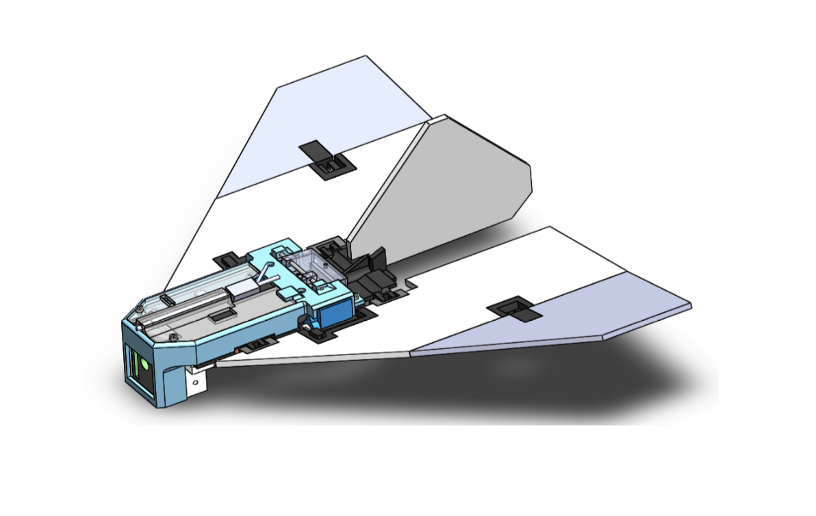
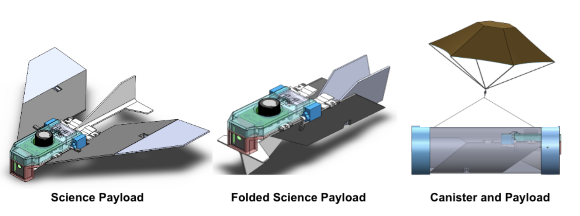
Shown above is an overview of our mechanical subsystem. The payload structure is made from a 3D printed ABS components that consist of a base plate, as well as electronic, battery and air particle sensor mounts. The base plate also stores servo motors that rotate the wings about their hinged axis’. The two part folding wing design is made of joint fiberglass- ABS material design to reduce weight. The canister is designed to fall horizontally and contains a compression spring loaded piston mechanism for easier deployment from the canister. The canister itself has two 3D printed ABS end caps as well as a LDPE sidewall sheet. The payload is ejected from the canister using a nichrome wire release switch, along with a fishing wire that runs through both the canister and payload.
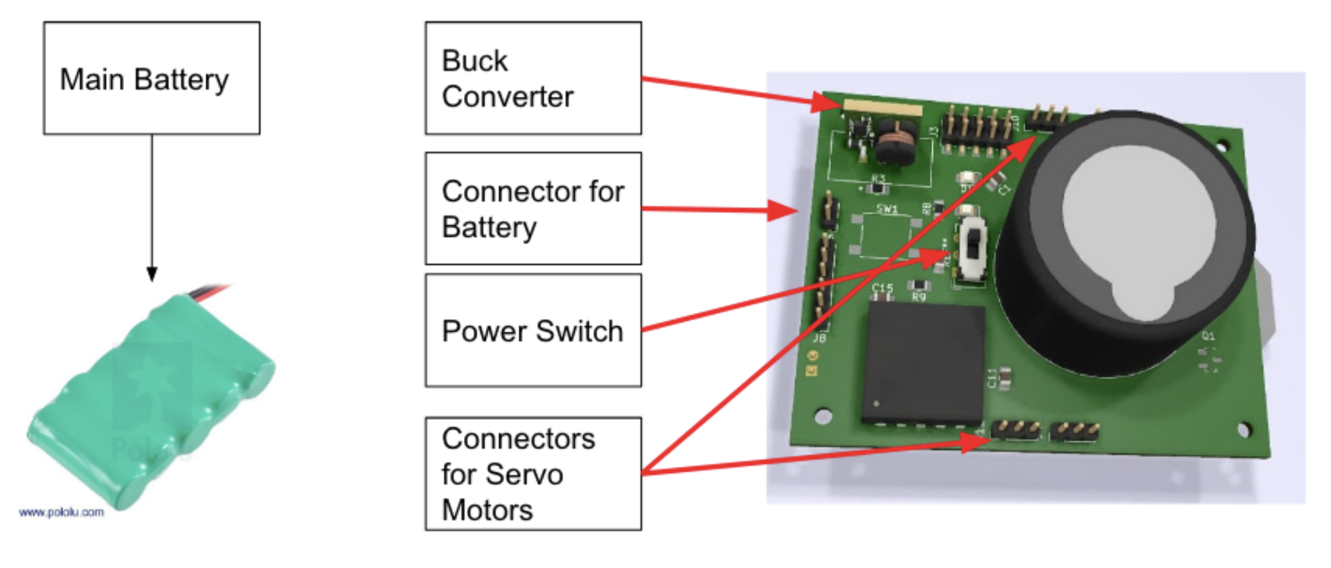
Figure: Diagram of the Electrical Power System components